 Now
you have finished modifying the OEM wiring harness and it's time to get down to
the business of installing the integrator unit.
Now
you have finished modifying the OEM wiring harness and it's time to get down to
the business of installing the integrator unit.
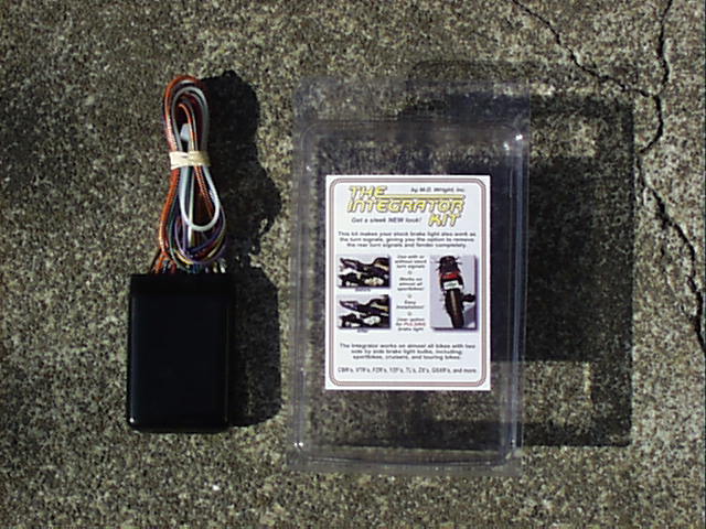
Remove the integrator parts from the packaging. At this time, you will need to decide if you want the pulsating rear brake light option. If you want the pulsating brake light, do not use any of the wire-taps included with the integrator. If you are following my directions, you will only use one of the red wire-taps so you can set the rest aside.
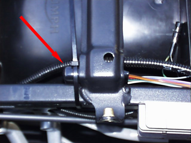 I
chose to mount the integrator unit directly beneath the seat support on the left
side (see picture). You probably will not want to zip tie it permanently in
place at this point, but place it there so you can measure the lengths of wire
you will need to run to each of the existing connectors. Refer to the wiring
diagram and legend and run the wires from the integrator unit to their
corresponding plug. Follow the approximate path that the wire will use in the
final installation. Give yourself a little extra wire and mark the spot on each
wire where you will make the cut. Remember, measure twice and cut once. Again,
if you are not going for the ultra-professional look, you don't have to cut any
of the wires leading from the integrator, you will just end up with extra wire
to hide but it will function the same.
I
chose to mount the integrator unit directly beneath the seat support on the left
side (see picture). You probably will not want to zip tie it permanently in
place at this point, but place it there so you can measure the lengths of wire
you will need to run to each of the existing connectors. Refer to the wiring
diagram and legend and run the wires from the integrator unit to their
corresponding plug. Follow the approximate path that the wire will use in the
final installation. Give yourself a little extra wire and mark the spot on each
wire where you will make the cut. Remember, measure twice and cut once. Again,
if you are not going for the ultra-professional look, you don't have to cut any
of the wires leading from the integrator, you will just end up with extra wire
to hide but it will function the same.
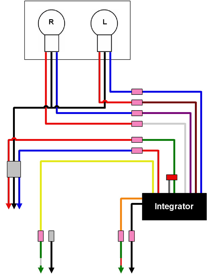
As you can see in the diagram, I chose to forgo the pulsing brake light option. I felt that the rear light acting as turn signal, brake light, and flasher was too much. If you do not want the pulsing brake light, bridge the short gray wire and the green wire leading from the integrator using one of the wire-taps included with the integrator (see diagram). If you want the pulsing brake light, leave the gray wire as-is. From this point on, exclude the gray wire from any future instructions.
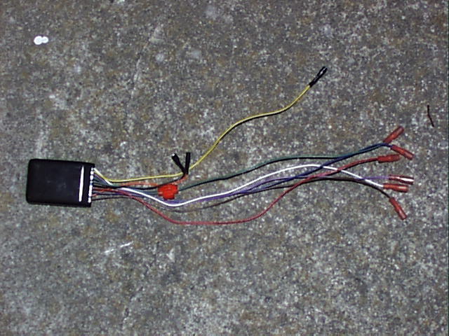
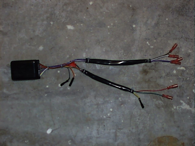
After you have marked and cut the wires coming from the integrator unit, install female bullet connectors on all of the wires except the yellow, orange, and black wires. On these wires, you will want to install male bullet connectors in order to mate with the existing female connectors on the OEM leads. If you use the same bullet connectors as the rest, you will need to gently crush these male connectors so that they mate properly with the female connectors on the OEM leads. I was unable to find any bullet connectors that fit into the OEM leads without this slight modification. Luckily, it's a very easy modification to make. Otherwise, cut the OEM leads and place a female connector on those. However, I tried to make this process as "reversible" as possible and so I wanted to leave the OEM leads as-is. After you complete this step, your integrator should look similar to the left picture below. After checking that everything would reach, I shrink wrapped the wires as in the right picture below.
At this point, I connected everything on the bike and tested the whole setup.
Remember to connect the battery ground if you disconnected it earlier. You
should check the functionality of everything at this point including brake
light, turn signals, tail light, and flasher, if you chose to enable it. One
note here, it is not necessary or advisable to start the motorcycle when
 performing
these tests. You certainly want to be able to hear or smell fuses popping or
wires melting in case you got something wrong. However, be sure to start the
bike every few times you turn the key to the "run" position.
Otherwise you will flood the engine and have a bear of a time getting the thing
started. I learned this lesson the hard way.
performing
these tests. You certainly want to be able to hear or smell fuses popping or
wires melting in case you got something wrong. However, be sure to start the
bike every few times you turn the key to the "run" position.
Otherwise you will flood the engine and have a bear of a time getting the thing
started. I learned this lesson the hard way.
After you have run all your checks and everything is working normally, install the integrator back into the bike and zip tie it firmly into place.